Birth and Death Use Case
This is testing code that demonstrates how to use SAF to output a mesh in which elements are being created and destroyed over the course of a simulation. The bulk of the code here is used simply to create some interesting meshes and has nothing to do with reading/writing from/to SAF. The only routines in which SAF calls are made are main, OpenDatabase, WriteCurrentMesh, UpdateDatabase and CloseDatabase. As such, these are the only Public functions defined in this file. In addition, the function to parse a sequence of addition/deletion, GetAddDelSequence, steps is also public so that a user can see how to program this client to create a variety of interesting databases.
The test is designed to be relatively flexible in the dimension of mesh (topological and geomertic dimensions are bound together) and in the various steps it goes through creating and deleting elements. However, elements are created and deleted in slabs (e.g. planes of elements). There is a default dimension and sequence of steps hardcoded into this test client. In addition, this test client is designed to also accept input from a text file that encodes the dimensionality of the mesh and the series of steps of deletions and additions (see GetAddDelSequence).
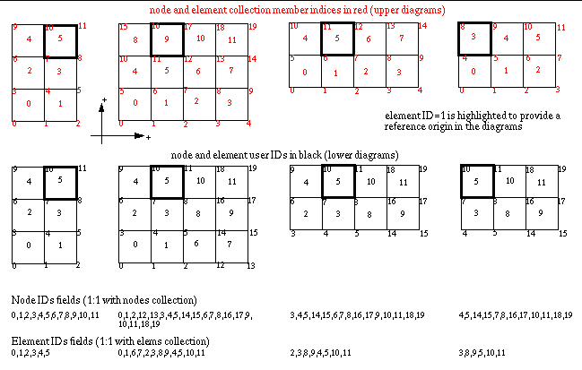
For each step, this test client will output the mesh set, its topology relation, its nodal coordinate field and the node and element IDs on each instance of the mesh. All mesh instances are collected together into a user-defined collection on an aggregate set representing the union of the different mesh instances. In addition, the test client will create subsets (blocks) of the mesh for the various half spaces in which the mesh exists. For example, for a 2D mesh, it will create, at most, 4 blocks for the (+,+), (-,+), (-,-) and (+,-) quadrants of the 2D plane. Such a subset will only be created if, in fact, a portion of the mesh exists in that particular half-space. We do this primarily to add some interesting subsets to the mesh.
Next, unless ‘-noSimplices’ is specified on the command-line, some of these blocks are refined into simplices. Those blocks that are refined are those whose low order 2 bits of the half-space index yield 2 or 3. In two dimensions, each quad is refined into 2 tringles. In three dimensions, each hex is refined into 6 tets. We do this only to make the element type generated by the code non-uniform.
If no arguments are given, the database will consist of a single file and the four mesh steps depicted in “use case 4-1.gif” will be produced. The node and element IDs will be as defined in the diagram.
