Dynamic Load Balance Use Case
This is testing code that demonstrates how to use SAF to output a mesh in which elements are being shifted amoung processors between each restart dump. The bulk of the code here is used simply to create some interesting meshes and has nothing to do with reading/writing from/to SAF. The only routines in which SAF calls are made are main, OpenDatabase, WriteCurrentMesh, UpdateDatabase, CloseDatabase and ReadBackElementHistory. As such, these are the only Public functions defined in this file. If you are interested in seeing the private stuff, and don’t see it in what you are reading, you probably need to re-gen the documentation with mkdoc and specify an audience of Private (as well as Public) with the -a option. If you are viewing this documentation with an HTML browser, don’t forget to following the links to the actual source subroutines described here.
This use case can generate 1, 2 or 3D, unstructured meshes of edge, quad or hex elements, respectively. Use the -dims %d %d %d command line option (always pass three args even if you want a 1 or 2D mesh in which case pass zero for the remaining arg(s)). The default mesh is a 2D mesh of 10 x 10 quads.
Upon each cycle of this use case, a certain number of elements are shifted from one processor to the next starting with processor 0. This shifting is continued through all the processors until the elements again appear on processor 0.
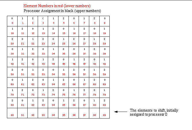
In the initial decomposition, elements are assigned round-robin to processors. This is, of course, a brain-dead decomposition but is sufficient for purposes of this use case. However, before the round-robin assignment begins, a certain number of elements are held-back from the list of elements to initially assign. This is the number of elements to be shifted between processors. By defualt, this number is 10. You can specify a different number using the -numToShift %d command line argument. These elements are the elements of highest numerical index in the global collection of elements on the whole mesh. Thus, in the default case, elements 90…99 wind up as the shifted elements. Initially, these elements are assigned to processor 0. Then, with each cycle output, they are shifted to the next processor. Consequently, in each cycle output by this use case, the element-based processor decomposition is, indeed, a partition of the whole. No elements are shared between processors. This decomposition is illusrtrated for the default case run on 3 processors in “loadbalance diagrams-2.gif”.

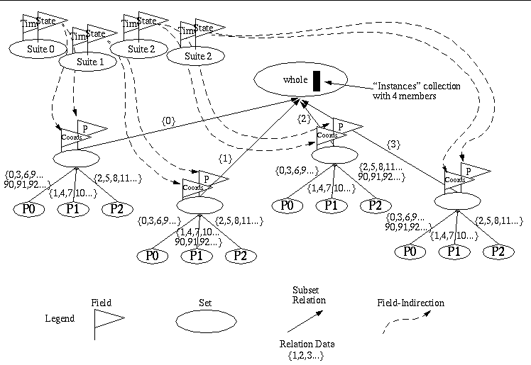
Since each cycle in the output is a different decomposition of the whole, we create different instances of the whole mesh in an self collection on the whole. The interpretation is that the top-level set and every member of the self collection on that set are equivalent point-sets. They are, indeed, the same set. However, each is decomposed into processor pieces differently.
Two fields are created. One is the coordinate field for the mesh; a piecewise-linear field with 1 dof for each node in the problem. The other is a pressure field with the following time-space behavior…
1 2 3 4 5 | 2
t
-------
2
(1 + r)
|
where t is time and r is distance from the origin. This is a piecewise constant field with 1 dof for each element in the problem.
Finally, both the the coordinate field on the whole on the given dump and the pressure field on the whole
are written to a state-field. Due to the fact that the state/suite interface does not currently support
subsuites (that is subsetting of a suite) we are forced to create a separate state/suite for each dump. This
will be corrected in the SAF library shortly. A high-level diagram of the Subset Relation Graph (SRG) is
illustrated in “loadbalance diagrams-2.gif”

Note that this diagram does not show the field indirections from a particular decomposed set to its processor pieces. That would have made the diagram even busier than it already is.
Optionally, this use case will output the dump history of a given element you specify with the -histElem %d
command-line option. Within the context of this use case, we define the dump history of an element to be
the sequence of processor assignments and pressure dofs for each dump cycle of the use case. If you specify
an element number in the interval [N-numToShift…``N``-1], where N is the total number of elements in the mesh,
the element’s processor assignement should vary, increasing by one each step. Otherwise, it should remain
constant. This so because high-numbered elements are shifted while low-numbered ones stay on the processor
they were initially assigned to.
An element’s dump history is not output by default. You have to request it by specifying the -histElem %d command-line option. Also, to confirm that the use case does, indeed, query back from the database the correct dump history, it also computes and stores the history as the database is generated. At the end of the run, it then prints both the history as it was generated and the history as it was queried from the database for a visual inspection that the results are identical.